There are a huge number of connectors for computer hardware. Generally, many arose from standards wars where different organizations wanted their standard to become the dominant one, so they could charge a license fee to use it. While this competition can help push the boundaries of what’s possible, it is obviously not consumer friendly to require higher prices to use a connector, cable, or protocol.
Thankfully, those days are generally past, with USB being an open standard dominating the peripheral connectivity market. As much as competition can be good, the dominance of USB also means you don’t need to worry if your mouse or keyboard has a suitable connector to work with your computer.
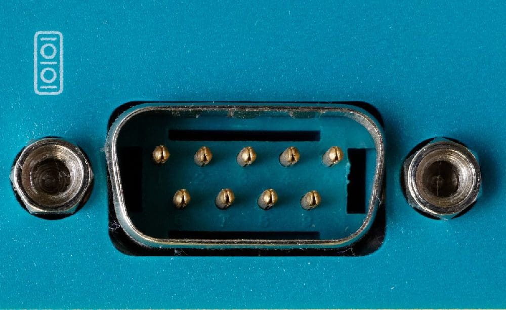
9-Pin Dsub
One of the early connectors was the Serial port. The physical connector used was, generally, the 9-pin Dsub called DE-9, which was first used on the IBM PC-AT in 1984. The D-subminiature connector standard had a broad range of connectors. The DE-9 had nine pins arranged in two rows. The “D” in the name comes from the D-shaped metal shield that runs around the connector pins. This shield helps to prevent physical damage to the pins when unplugged, connecting, and disconnecting, and helps to take some of the strain when connected. It also provides some protection from electromagnetic interference.
The final part of the physical connector was a pair of optional screws on either end of the shield. While these increased the size, they also helped take the mechanical strain, helping minimize the risk of cable damage. The “subminiature” part of the name may sound a little laughable compared to the far smaller USB-C and eSB-A connectors on modern devices. When the standard was published, however, D-sub connectors were amongst the smallest on the market.
Tip: You may have seen a similar connector on the back of some monitors. The VGA monitor cable used a 15-pin D-sub connector DE-15, typically colored blue. While superseded now by HDMI and DisplayPort, VGA was very popular for a long time.
Parallel vs. Serial
Many of the connector standards at that time were parallel. This meant t a large number of data pins that all transmitted data in sync. This approach had two main issues. First, you need many electrical pins to operate this way, making connectors large and unwieldy.
The second is that synchronizing these large arrays of connectors is tricky and gets harder the more often you transmit data. This essentially limits the maximum frequency at which you can share data. The only way to increase bandwidth further is to make connectors with even more data pins.
A serial connector uses a single data connection, though there can be multiple side-channel pins and multiple data lanes. It’s essential to ensure that there are two data connections, one for transmission in each direction. Using a small number of connector pins allowed significantly smaller connector sizes. This enables complete duplex transmission allowing bi-directional communication at full spec speeds.
Uses for Serial Ports
The serial port was popular for various network, and peripheral connection uses. Its use is easy now, but it can still be found in some use cases. Networking hardware, mainly managed routers and switches, often offers a serial port as a local connectivity option. It’s not intended to be used as a network port, as the bandwidth is incredibly low, around 10Mb/s.
However, performing diagnostics or firmware updates can be helpful if network connectivity to this functionality is somehow compromised or disabled for security reasons. Modern computers tend not to have a serial port to connect with, so a USB adaptor is typically necessary. Cables that have an ethernet port at one end are also available.
One thing to be aware of with serial ports is the difference between data terminal equipment (DTE) and data circuit-terminating equipment (DCE), as different cable variants may be needed. Devices are generally configured so that a DTE device needs to connect to DCE devices. As such, the in and out pins are intentionally flipped on DCE vs. DTE devices. This means you can use a straight cable that keeps all the pins in the same order.
Unfortunately, if you want to connect two DCE or two DTE devices, you need a cross-over or roll-over cable. This type of cable flips the in and out wires to allow them to be the same on each device. Most modern devices contain an auto-detection feature, adapting to the use of either cable. This was not a common feature in earlier implementations. DTE devices are user devices such as a computer or managed network hardware. DCE devices tend to connect to other communication media, like a modem.
Conclusion
The serial port is a computer connector port. It was initially introduced in 1984 on the IBM PC-AT and still has a few uses, though it has been largely superseded. It uses a 9-pin D-sub connector known as DE-9. In modern devices, it is essentially exclusively found on managed network hardware. The connector is visually similar to the VGA cable but has a lower pin count version.